Gary Adcock
Stereographer, Instructor
Last Sunday, I was asked to present an introduction and overview on 3D and 3D production and alignment procedures to the Midwest members of the Camera Union. Working with Daufenbach Camera’s Element Technica Quasar style 3D rig, we offered some of the locals an inside look at what it takes to properly align and control a well-maintained 3D rig.
Initial alignment of most beam splitter rigs, like the ET Quasars I have worked on, starts with the “zeroing” out of the two cameras, aligning them with a great deal of precision to each other. My rig-techs and stereographers I know still use the simplest charts for this base alignment, most often using something as simple as a B&W “Siemens star” normally reserved for backfocus adjustments.
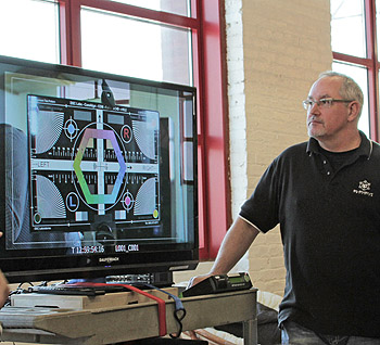
However, after that base alignment is finished, the DSC Fairburn 3D chart is dragged out to the main stage. This 3D chart’s complexity benefits users with all its lines and rules and color indicators, allowing me to see the alignment and mirror box issues that will allow me an incredibly fine adjustment to tweak the camera – so that we will not have to compromise either alignment or miscalculate matching irregularities between lens pairs.
This final alignment of the rig, often including “secret” mirror box adjustments, is one of the points that separate a production. The vastly more expensive, self-contained 3D systems used for broadcast can handle these adjustments and corrections during their boot-up calibrations, but the cinema style rigs like ET’s Quasar, require adjustments to be done manually. Including a short clip of the chart on every show allows production and post the benefit of having truly accurate references – distance, inter-axial distance with color and grayscale reference points. These ensure both accurate alignment and color consistency on both cameras, regardless of mirror discrepancies, or light and chroma loss when shooting thru, or at, the reflection on your beam splitter.

